ex01_ant_rf
This example removes the existing topography from the Cascadia ANT+RF
shear-wave velocity model with -Or+t and then adds dry-land topography
to that flattened model with -Oa+t using each of the three topobath construction
methods. Wet columns remain outside the selected operation scope.
The shared Earth relief grid is a one-arc-minute crop of GMT’s
@earth_relief_01m_g dataset over longitude/latitude =
-130/-116/39/52. The script creates and caches this 1 MB regional grid if
it is unavailable. All topobath operations use the smaller local file.
The ANT+RF model stores depth in kilometers, positive downward. The relief
grid stores elevation in meters, positive upward, so
+z-0.001+Zkm converts its values to the model convention before sampling.
The output axes increase from the top (zmin) to the bottom (zmax):
-T0/10/0.1   flattened model from 0 to 10 km depth
-T-5/2/0.1   topographic models from 5 km elevation to 2 km depth
The deeper flattened model retains enough source material for columns shifted upward by the pull-up/push-down method; the figures display only the upper 2 km.
The model uses zero as its shallow water or air marker. -WVs/0+t0.01
therefore identifies old water columns and writes zero shear-wave velocity
where new bathymetry creates water. -Dh -A0/0/1 uses high-resolution GSHHG
ocean and land polygons as the inference prior. Columns outside the ANT+RF
model coverage remain NaN.
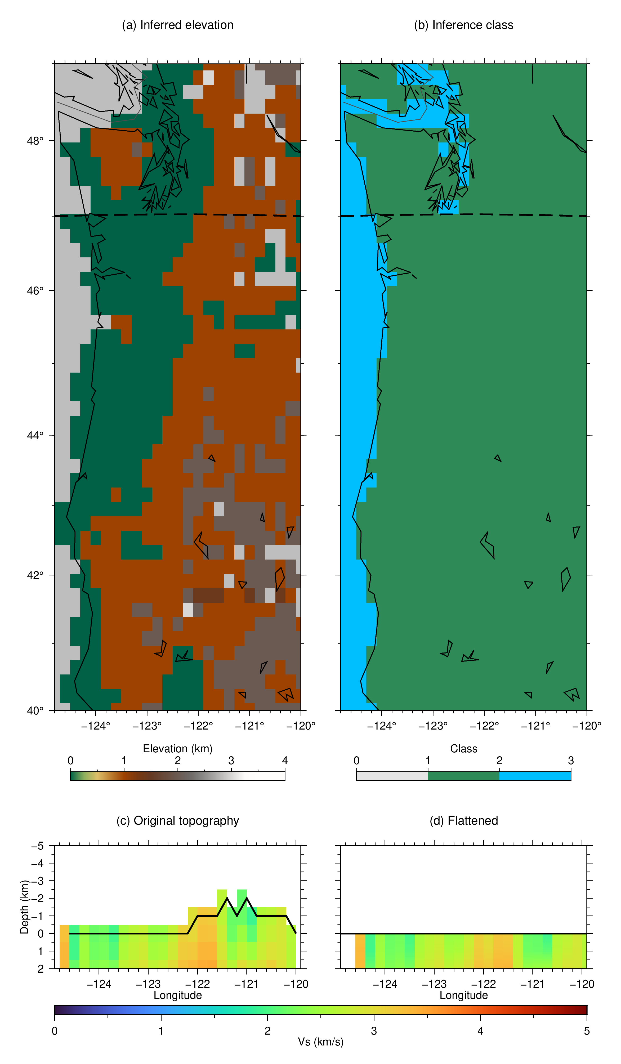
The diagnostics figure contains the inferred elevation, inference classes, the original latitude = 47 N section, and the flattened section. Class 0 marks unresolved columns outside the model coverage, class 1 marks land, and class 2 would mark a seafloor inferred from water values.
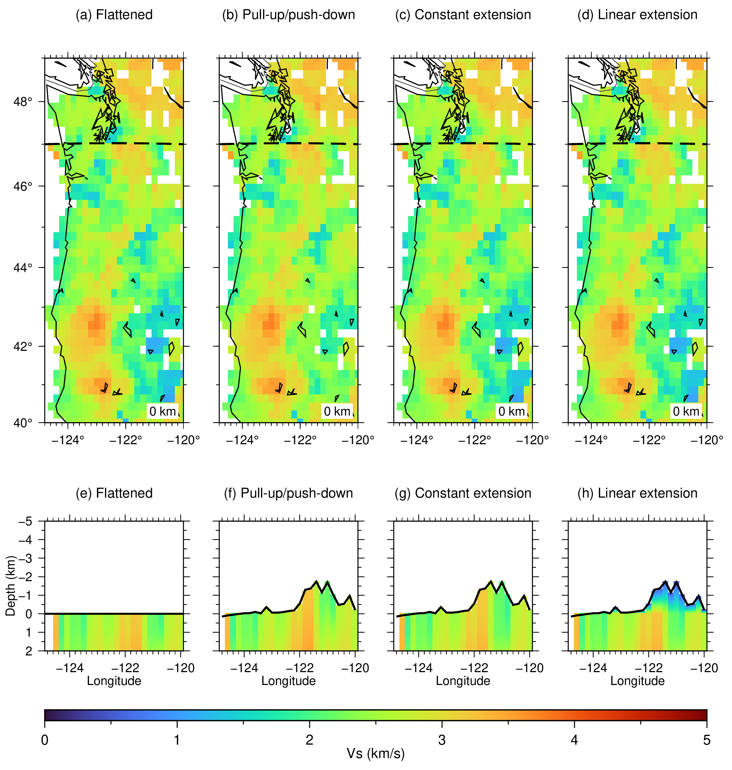
The methods figure compares the flattened baseline with:
-Oa+t -Mp: pull-up/push-down construction-Oa+t -Me: constant one-dimensional construction-Oa+t -Ml -LVs/0.5: linear construction to 0.5 km/s at the land surface
The top row shows Vs at zero depth. The bottom row shows latitude = 47 N sections from 5 km elevation to 2 km depth. Dashed lines on the maps mark the section location, and solid lines on the sections mark the applied surface.
Run:
./ex01_ant_rf.sh
Intermediate NetCDF models are removed when the script exits. The script creates:
ex01_ant_rf_diagnostics.pngandex01_ant_rf_diagnostics.pdfex01_ant_rf_methods.pngandex01_ant_rf_methods.pdf
Figures